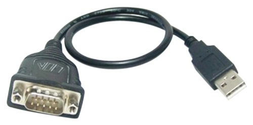

So I removed a resistor to free up the trace and soldered the 100nF cap right in there, it wasn't terribly hard, in spite of the minute lead on the CP2012. This is my first one, so it's news to me and I find it hilarious!!! Both USB-Serial adapters I used, the Arduino USB2SERIAL and a CP2102 clone needed the cap between the DTR pin and /RESET, even though both have the DTR pin marked as RST.Īs a side note, the CP2102 module had RST connected to the reset pin of the CP2102!!!.My test board didn't have that pull-up, which I usually hide right under the 1284, so I was scratching my noodle as to why I am not seeing any sign of a reset on this particular board, but it was working on two others In order for the 100nF cap to work, the 10K pull-up on the /RESET pin must be present.Optiboot for 1284p needs to be compiled with BAUD=19200 (that is why it wasn't working, but worked on the 328p).There are a few important prerequisites, and here they are for further reference: Update: The setup works fine, even with the 1284p. Once you verify it works ok with the Uno, you will know if you connect it to the 1284p and it doesn't work, the problem is isolated to just the bootloader. Proceed with Uno which has been tested and is known to upload sketches through the USB port.Ĭonnect the USB to Serial adapter to the computer, select the USB to Serial port in the IDE, and upload a sketch. You can bridge a solder blob or small wire across the jumper later on, to restore the Uno. Can you cut the RESET-EN jumper pad of your Uno? If you do, then you can test the full functionality of the USB to serial adapter with your Uno, including the auto reset part of the circuit, and you will know exactly how to connect it to your 1284p. That way you would eliminate that part as an unknown. I suggest taking the approach of validating exactly what your USB to serial adapter does, and re-visit getting it working with your Uno. I use a FTDI Basic clone from for offboard USB/Serial adapters, couple examples: an Arduino Ethernet board) through a 100 nF capacitor, allowing the board to reset on upload." It's typically connected to the reset line of the connected board (e.g. The external reset line mirrors the DTR line of the virtual serial device on the computer. The USB Serial connector is designed in a way that allows it to reset an attached board by software running on a connected computer.


 0 kommentar(er)
